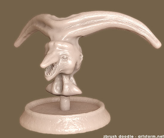
It was time! Time at last to bring one of my creations into another renderer than ZBrush.
I doodled up something in ZBrush and moved it into LightWave 3D for rendering this time. Below is a rendering of my only 2470 polygons large mesh inside of LightWave with a displacement map.

First try to combine ZBrush and LightWave 3D
It did actually take some time and experimentation until I got it right, but in the end I did find a good flow for the process of getting ZBrush data into LightWave 3D.
I started with a quick doodling session in ZBrush. The usual procedure. Draw out a couple of ZSpheres to get a base mesh, divided it a couple of times, and sculpted for about 30 minutes to get something with enough details in to work with and find my flow between the applications.
It took a few turns back and forth and quite some head scratching until it worked smoothly. I ended up working in this way. First the ZBrush part.
- Bring the mesh down to the lowest resolution.
- Group the UV tiles (It’s not a pretty UV map created this way, but it was okay for this experiment as I wasn’t about to work on the map in any other application anyway).
- Enable adaptive displacement, raise the intensity to max, enable displacement mode and finally set my output resolution to 4096 pixels and run create displacement map.
- Export my base mesh with flipped quad polygons as an .obj file and also export the displacement map flipped vertically as a tif image.
And we’re done in ZBrush, let’s move on to the LightWave part.
- I imported the .obj in Modeler and turned on subpatching, saved it as an .lwo and moved on to Layout.
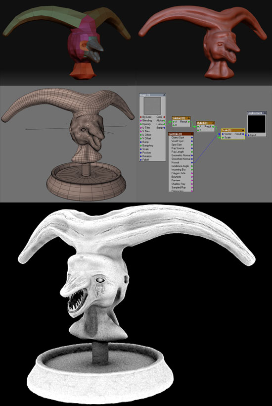
- In Layout I made a displacement node flow, consisting of the displacement map image fed into a subtract node. As medium gray in the displacement map is pushed out in LightWave and it’s supposed to be 0 in ZBrush measurements, I subtracted 0.5 from it. Then a multiply node to control the height of the displacement and finally I ended up feeding it into a scale node combined with the normal spot info node. Done, a perfect ZBrush displacement inside of LightWave.
Before rendering I enabled LightWave’s APS system, Adaptive Pixel Subdivision, and set a gradient on the Angle to the camera’s Z-Axis to get enough polygons for detailing at render time without killing the engine. And for fun I also slapped on a SSS shader node flow to make it a bit more interesting. F9! And we have a scene with 2470 polygons rendered as 1.4 million polygons with lot’s of lovely details!
Here is a tiny visual step by step guide all the way from ZBrush into LightWave ending up with an Ambient Occlusion render.

Visual Steps from ZBrush to displaced LightWave render
I hope this information will be found useful to some people.
Anyway, next time I will make the final step, bringing one of my 3D meshes out from LightWave and into ZBrush, sculpt details on it there and then bring it back to LightWave again for rendering.
Doodling Music: Air – Pocket Symphony
